Showing posts with label hacking. Show all posts

15 May 2015

Fixing the power connector on Apple Cinema Displays (Aluminium)

Author's note: wiring done by dgorbik; writeup by yours truly

It turns out that after a while, if the power cable from the display is bent near the neck of the plug, the plastic clamshell over the plug will separate. Not only that, the cord will slowly stiffen and any bending motion will detach the wires, shielding, and epoxy from the metal connector. I have no use of a dead display (and am unofficially retired from the display-splicing scene), I gave my dead 30" Apple Cinema Display to my friend.

Not the 150W brick; they look similar. Source: Google Images.

It also turns out that the Cinema Display power connector looks very similar to that of the first generation Mac mini. Recall that the mini used an external 85W power supply, where one end was a reversible female 10-pin connector (2 sets of 5 pins) and the other end was an IEC Mickey Mouse connector. In fact, that 10-pin connector is, empirically, identical to the one used on the Cinema Display. I had one of those bricks so I gave it to my friend. He quickly cut both cables, revealing a red and black cables, and a thinner gray cable within the shielding.

Source: Google Images.

Simply color matching and soldering the cables didn't do the trick. My friend and I tried 3 different power bricks (150W), 3 different graphics cards, and 2 computers to no avail. Metering the donor cord appeared to give a bad reading, but turns out the wiring was backwards! (Tsk tsk Twiggy/Q88 team). So soldering black to red, red to black, and ignoring the gray wire worked.

Source: friend.

24 September 2011

MiniHack: Shelf G5

So how did that get up there?!

A much larger scale and more public hack

19 September 2011

New [School] Year, New Setup

I had these nice IPS screens laying around, so why not use them? (Please don't remind me of my lack of mini DisplayPort -> * adapters [1])

Triple displays driven off a...Power Mac G4 [2]?!

 I ought to do ``real work'' instead of reading random papers...

[1] Over the summer, I acquired a Biostar Radeon HD 6870, which did not come with any mini DisplayPort adapters. Last week, I ordered a handful adapters, but they have yet to arrive despite the 3-4 day shipping. I longed for the setup ever since leaving Apple (where I had a dual 27" + 21" setup -- a glorious six megapixel arrangement), so initially I tried using my crufted Matrox DualHead2Go Digital, but that didn't work because the highest analog resolution the 6870 supported over DVI was 2048x1536, which was a few pixels short from the requisite 2560x1024. I then asked a friend for a PCIe x1 card since my mATX motherboard had a free and unobstructed x1 slot, and lo and behold, I am running a Nvidia Quadro NVS 290 to drive the Dell U2211H and the Radeon to drive the Apple Studio Displays (which, by the way, the one on the right is my personal hacked monitor -- shameless plug for myself).

[2] I ought to write up my Power Mac G4 case mod someday. Maybe on Wednesday, which is a student holiday for me!

[EDIT 20 Sep 2011] Yes, I'm running Windows. No, I don't have the time to fix my Linux partition and pray for both Nvidia and ATi drivers to work together peacefully. Nor do I have time to hackintosh. Any more questions?

16 November 2010

I'm Still Alive...I think!

Hey folks,

Apologies for the lack of movement/posts in the last week or so. Another week of exams/projects is coming up, so I don't have the luxury of heading to MITERS on Friday nights to tinker around. Actually, I don't have time to break from studying or coding to mess around with the display, which happens to be sitting a mere foot behind me. :/ So yeah, in short, life at MIT is very busy!

What I've been up to recently: learned Cilk, an x86 parallel programming platform invented by my professor, Charles Leiserson (the tech has been acquired by Intel last year). I used it to optimize a graphical screensaver (6.172 Project 4 [pdf], if you're curious).

I also got my hands on two very sexy pieces of hardware:
  1. a 13.3" MacBook Air 1.86/4/128/320m as a replacement for my 4.5-year-old, trusty Core Duo MacBook Pro (2.0/2/160GB Intel G2/X1600). Expect a review within the next week.
  2. a 15" iMac G4, courtesy of Bayley (the dumpster diver) =D
Awwww, so cute :3

I'll write some brief notes about the iMac, even though you are probably more excited to hear about the MacBook Air. The iMac boots Mac OS X 10.2.8, but since I didn't have the password accounts to any of the existing accounts, I found a hack to let me get in by making a new account with admin rights. All you have to do is boot into single user mode, remove /var/db/.AppleSetupDone, and reboot! The Mac will think this is the first time the computer has been booted, so it will go through the traditional setup process. After approximately five minutes, I had my own account with admin privileges! =D What an easy and terrifying exploit. So much for `security' in older Mac OS X versions ;)

Besides that, the Mac has a 1GHz G4 processor, 256MB RAM (though easily upgradeable considering the vast amount of DDR RAM sitting in my drawers), and a semi-spacious 80GB disk. I theoretically could dump one of my many disks currently sitting in my dresser into it. That might make a good Thanksgiving project.

In other news, I am teaching three Splash classes: Bit Hacks by myself, and two bridge classes, Probability in the Game of Bridge and a Menagerie of Bidding Systems, with my partner-in-crime Brian Hamrick. Lecture notes and slides will be posted for your enjoyment :)

And finally, Math Prize for Girls was this past Saturday. Congratulations to all! The score distribution was much better than that of last year, with a tie in 3-5 and a ten-way tie for 8th place. The competition (and the fact that I got a MacBook Air not too long ago) reminded me of my [very silly and naive] vow if I had won the competition last year (going to the nearby Apple store to buy ten decked-out MacBook Airs immediately following the competition).

In any case, happy hacking!

08 November 2010

Apple Display Hack Followup

Here is a link to the original post: http://doesntexistat.blogspot.com/2010/11/hacking-apple-studio-display.html

Intro, Power Supply

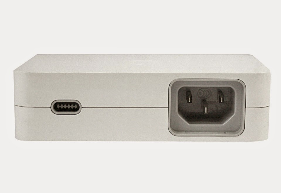
So this past week was exams week, which means that I did not get much time to work on the project. After exams were over on Thursday night, I opened the 24V 1.5A power supply that I got from ebay! The cute power supply is pretty small; about the size of 5x7 photograph. There are terminals for AC +, AC -, AC Gnd, 24V +, and 24V -; you unscrew a screw which secures a plate, which in turn sandwiches the wire in the middle of said plate and the power supply unit itself. I then stripped one of my many computer power cords so I could use a 3-pronged plug. Most 3-prong plugs have black as L (line), white as N (neutral), and green as ground. No soldering or nonsense was needed to wire, since the only effort to wire up the system was unscrewing five screws and inserting the wires in between the plates and the unit itself. Before I wired up the monitor power cables to the power supply (and after I had attached the AC power cord), I measured the output with a voltmeter, and sure enough, it read 24.5V! Perfect.

Wonky Connections

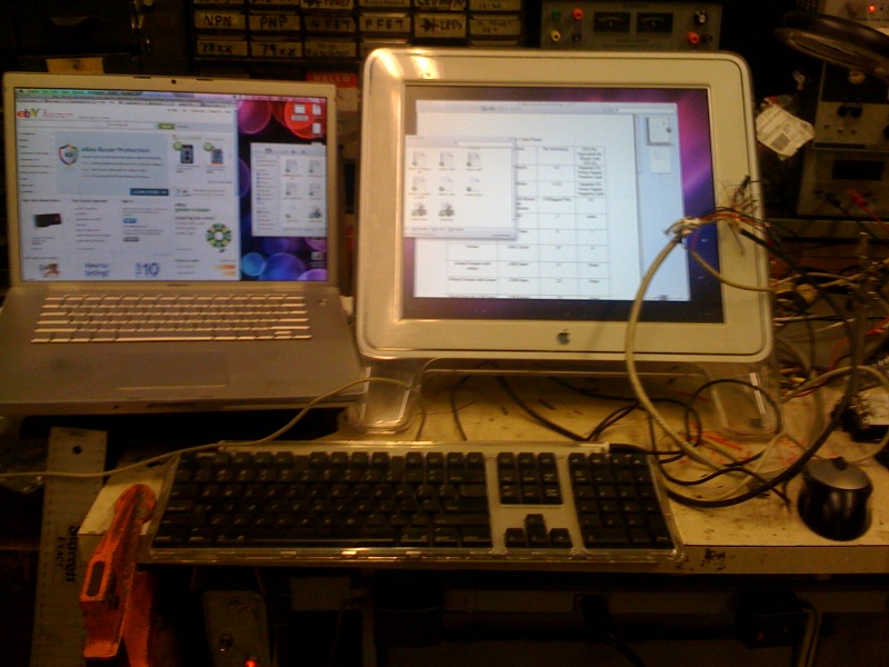
I then wired up the monitor, plugged in the setup, and powered on the system. Sure enough, the monitor came to life! Upon closer inspection, I noticed some pixels that were spazzing green (i.e. flashing green and the proper color). This was probably a problem with the cable connection; I smacked the mess of wires and the number of spazzing pixels reduced.

The spazzing goes away if I squeeze the proper connections. This confirms that some connections are loose. I can temporarily fix the problem by holding the connections with a binder clip, but will resolder and/or reshrink the connections once I get a soldering iron in my room. There is no way I am lugging the monitor 1 mile across campus again.

Setting up a ghetto dual screen setup in the middle of a dorm (Random Hall) kitchen warrants weird looks!

USB & Hotplug

Apparently USB was always working. I finally tested it today with an Apple USB mouse. It's good to know that the monitor extracts/produces/ the +5V required internally. I still have yet to figure out hot-plug support (I guess it is a matter of soldering two wires together).

Display Brightness

I hadn't really thought about this until I skimmed through the bit-tech thread for the clean version of this hack. As all Apple display owners know, the brightness is controlled through software (System Prefs on a Mac), and the button on the display is more or less an app launcher for System Preferences. I confirmed that pressing the button works -- it brings up System Prefs to the Display pane. Dragging the display brightness does change the brightness!

Other people mentioned that the display will draw significantly current at a high brightness than at a low brightness. When I tested the display (at full brightness) with the lab power supply, it drew less than 1.5A, so no worries there.

Breakout Box

I thought about making a breakout box as the true solution to this problem. I was fortunate to find a video card with a female ADC port in the dumpster. In theory, I could desolder that, create my own PCB board, and solder the necessary parts on (female ADC port, female DVI port, connection to power supply, USB cable). Unfortunately, desoldering the ADC port from the video card was crazy evil (especially at 12:30am), so I stopped working on it for the evening. Perhaps the desoldering tool needs a smaller head (it was one of those powered heat+vacuum tools). I will give it another shot when I return to MITERS.

Miscellaneous

One of my friends also got a 15" version of this monitor and creatively mounted it on his bunk bed after stripping off the acrylic (which is equivalent to unscrewing seven hex screws). He is also planning to do this hack! I am happy.

Feedback and Q&A

I also read much of the feedback to this hack. Thanks all who appreciated it. I do realize that this hack is not original (in fact I did not claim to be the first one to have done so since I linked to someone's pinout guide in the main post), but I do claim that this is my first hack. I do want to congratulate WarriorRocker for his very clean and Apple-esque Apple Studio Display hack.

Now, to answer some questions/feedback:

Q: ...pinouts.ru...
A: Yes, I'm well aware of it. However, soldering the pins on the plug to wires is tricky, and since this is my *first* time soldering, I'd rather do something more manageable. I'm sure the hack will be a lot easier had I just connected corresponding pins with wires. Thanks anyway!

Q: I happen to be attempting the same thing and I seem to be running into a snag. The only video connections I've made are the 8 which come off the board - Clock +/-, TMDS 0+/-, TMDS 1+/-, and TMDS 2+/-. Is there anything else that is necessary for DVI to work that I'm missing? Also, I'm using a 24V 4A power supply, could the amperage be too high? The power button lights up and pulses but I don't even see a flicker on the screen.
A:  Yes, you are missing DDC Clock (ADC pin 9) and DDC Data (ADC pin 19). Your power supply should be more than fine; the monitor is rated for 50W.

Q: Other Pins <=> Colors on the DVI fragment
Is there any number pin number?
Dvi or adc pin number ?????
A: The DVI pin numbers are on the left of the chart. Basically that chart was a listing of all the leftover wires after I had soldered everything according the the main chart. Apologies if that was unclear.

Again, a big thanks for all who thoroughly read through the post and appreciated it!

02 November 2010

Hacking the Apple Studio Display

I acquired a circa 2002 17" Apple Studio Display LCD in good condition from my friend and dumpster-diver-buddy Bayley Wang. The monitor is one of the top-notch 17" monitors: (Hey, it retailed for $999!) it has a superb IPS, or in-plane switching panel for unmatched color quality even by today's semi-professional standards (pros probably want 10- or 12-bit panels now). Unfortunately, this unit has an Apple Display Connector, or ADC, plug instead of the more standard DVI plug. On the flip side, the ADC is simply DVI + USB + 25V, so I could hack the monitor to use DVI! I looked on Google for previous hacks, but the only relevant documentation was a post and a PDF on the Apple discussion forums describing the ADC pinouts and their DVI equivalents. Having nothing better to do, I decided to splice a spare DVI plug onto the monitor!

Hacker food = McDonald's. Yup.

I began by cutting off the ADC plug from the single wire the came out the back of the monitor and then proceeded to strip off the rubber sheath, cut off shields, and strip the internal cables. The actual cables were 26-gauge wires -- they were very thin and looked very fragile! I used a magnifying glass to help peel off the shielding. Some of the internal wires were grouped and additionally shielded; I exposed them at a shorter length to prevent cable confusion (there were multiple cables of the same color). I repeated the process for the DVI cable: first cutting it in half, then stripping the wires, and finally stripping the wires which were enclosed in a further layer of shielding. Stripping all the cables took a good hour and a half.


The next item in our agenda was to find out which wires corresponded to which pins on the DVI wire fragment. I was not quite sure what to do initially, but a MITER gave me the following tip: Apparently the ohmmeter has the nice property of displaying some odd (i.e. zero) resistance when the positive and negative leads are connected without resistance. I tested all the pins and all the wires and constructed the following charts (note: these colors may be different for your DVI cable!):


Main correspondence table

ADC colorDVI Pin & Color (if none, function)
2x thick red+25V
2x thick blackGnd
very thin dark brownC5
very thin orangeLED
light blue 7 yellow (single)
yellow6 white (single)
green (twisted w/ white)USB D+
white (twisted w/green)USB D-
black (near USB Data)USB return
light brown (t. w/ white)24 white (white, blue)
white (t. w/ light brown)23 blue (white, blue)
white (t. w/ orange)2 red (red, pink)
orange (t. w/ white)1 pink (red, pink)
pink (t. w/ white)9 brown (yellow, brown)
white (t. w/ pink)10 yellow (yellow, brown)
white (t. w/ black)18 green (green, black)
black (t. w/ white)17 black (green, black)

t. = twisted
(color1, color2) = color1 is in the same shielded group as color2

Other Pins <=> Colors on the DVI fragment

11naked w/ yellow, brown
16light brown (single)
14dark brown (single)
15black (single)
3naked (red, pink)
22naked (blue, white)
19naked (green, black)

single = not in a shielded group

Male DVI-D (single link) pin numbers:

C5876------321
161514------11109
242322------191817

The --- pins represent unused pins; these pins are for dual link connections only.

I was left waiting for quite a bit because I didn't know how to solder and one of the MITERs who graciously volunteered to teach me, Dane, was busy with his project. After he was done, he soldered one of the wires on the monitor end with the corresponding wire on the DVI cable fragment while I watched from the side. Then he placed a heatshrink over the freshly soldered wire and blew it with a heat gun to prevent the conjoined wire from shorting the other wires. I then sat down for what seemed to be an hour and concentrated on soldering all the pairwise wires. The end product was a great big mess; Charles Guan, the MITERS god, felt sick to his stomach just by looking at it! Everyone doubted that my hack would work, but I had a sliver of hope that my first real electronics project would succeed.


After I was finished, I showed Dane the end result. He suggested that I should solder the shields (the naked wires in the shielded groups), too. I finished soldering rather quickly, heatshrinked them, and reported back to Dane. We then connected the monitor to the lab power supply, dialed it to the Apple-specified 25V, and connected the alligator clips to the red and black wires on the monitor. Dane touched the capacitative power button, which pulsed at the touch. I connected the monitor to my laptop, went into System Preferences, and hit `Detect Displays.' The monitor then came to life in mirror mode!! My five hours of hard work paid off!

 IT WORKS!!11!!oneone!

Mess of cables

Other notes:
  • USB does not work. I'll get that working this week. [EDIT] A friend suggested that the monitor might internally make the +5V required for usb, so I'll have to test it this week at MITERS since I don't have the power supply in my dorm. USB does work -- see the follow-up.
  • Hot-plug display detection doesn't work. I'll get that working this week.
  • I will consider making a breakout box instead of hacking the monitor cable. One of these adapters costs a whopping $99 from Apple! 
  • The monitor runs fine on 24V and draws slightly more than 1A -- no need for 25V. I have already ordered a 24V 1.5A regulated power supply from ebay.
If you have questions and comments regarding this hack, feel free to leave a comment (Google account required)!

EDIT[2]: Here is a followup of the hack: http://doesntexistat.blogspot.com/2010/11/apple-display-hack-followup.html

EDIT[3]: Here it is in action: lame dual display and insanely excellent triple display

30 October 2010

MITERS

Yesterday night, Bayley and I decided to head to MIT electronics research society, or MITERS, after hanging out watching people play League of Legends at Random and eating a hearty dinner consisting of tiny McDonalds' burgers. I figured this would be a good time to learn how to solder and hack the 17" Apple Studio Display (flat panel) with an Apple Display Connector (ADC) that Bayley gave to me, so I carried that along. The lab/warehouse was located a good minute's walk from Random, but walking with a rather large monitor tucked under my arm was rather troublesome. Once we got there, I found an empty lab bench and introduced myself to the MITERSers (should it be just MITers?), while Bayley got down to work with his laser. The hack, which I will elaborate in a future post, that I wanted to do was to convert the ADC plug (male) to a DVI plug (male). Sure, I could buy the breakout box from Apple for $99, but a ghetto setup for $0 would be much more awesome. It took about five hours to complete, from stripping the cables to testing the unit.

 Teaser image: My first real electronics project works!

Having nothing else to do, I hung around the lab and watched other MITERSers work on their projects and beta-test the 4-ft tall Tesla coil in the parking lot (this was at 3am today). The coil was particularly interesting in that it played loud, off tune music and had the peculiar ability of attracting drunk young adult females.


Bayley and I finally left around 4am, satisfied that our respective projects were successes.

27 October 2010

This Fated Moment

My printer "ran out of ink."

"Ran out of ink?"

Yes. The cartridge isn't actually empty; the printer, a Brother HL-2040 (a laser printer my dad purchased a few years ago for $50), is programmed so that when the toner level is below some threshold, will refuse to print any more documents. This means that I'll have to rely on the hall printer or some other Athena cluster printer, whose queue is usually jammed with 20-page articles people need to print for their humanities classes. Well, that's unfortunate.

[Interjection] The clever MIT student would say, ``Well, couldn't you just haul back any printer from the dumpster? They all work...'' To which I would respond: ``Hacking my current printer would be much cooler!''[/Interjection]

Actually not quite. A few years ago, when I was researching this particular printer in my leisure, I came across a highly insightful Amazon review (which I then stored in my Google Notebook):

135 of 136 people found the following review helpful:
Masking Tape Gives TN-350 Toner a Second Life,August 25, 2008
By C. MACPHAIL "cmacphail3" (Solana Beach, CA USA) - See all my reviews
(REAL NAME)       
I get 800 to 1100 extra copies from each cartridge.

After the "Toner Life End" message appears, it refuses to print even one more copy. Offensive...until you show it who's in charge.

Remove the cartridge and find 2 clear plastic port holes, one on each side. The printer shines a light through these to decide when to shut you off. But it's too sudden and too early.

Cover one or both windows with a small piece of masking tape. I get about 3400 copies per cartridge instead of 2400.

I really like Brother printers now that I have taught them some manners.

So I tried it...

Here is the hole on one side (close up).

Here is the hole relative to the cartridge unit.

Here is the hole covered by masking electrical tape.


...and hey, my printer now willingly spits out my biology homework!

The printer is nice and happy! (Green Ready light is on instead of the irksome orange Toner light).

For the keen eye: The processor sitting on my printer is a LGA775 Pentium 4.

Next hack: DIY ADC (female) to DVI (male) adapter! Stay tuned!

16 October 2010

iRepair Adventures, Dell Latitude D600 Part I

During my almost-daily runs to the Dumpster to search for goodies, I found this nice Dell Latitude D600! It was in fair condition: there were some scratches and dings on the top lid, worn out palmrests, and messy sticker removal traces on the bottom housing. Inspecting the externals, the laptop was missing its bottom-mount battery, but came with a bay-mount battery! GRanT, the 4E GRT (graduate residence tutor), graciously lent me his dell adapter (with a frayed charging end =P) so I could test the laptop. When I plugged it in, the charging LED came on. I tried to turn on the unit, but to no avail. Then I took the laptop to my desk and started unscrewing the bottom.

Before removing the bottom plate, I thought to myself, `Wouldn't it be a lot easier to check if it were missing critical components, say RAM, first?' So I unscrewed the RAM lid, and hey, both DIMMs were missing!

Good news: the wireless card is still there! [1]

So I took the computer home, found a 40GB IDE disk and two 512MB SO-DIMMs. One of the memory modules was rated at 266MHz and the other unknown, which might be a problem. I put in the components, plugged in the laptop, and pressed the power button. No cookie. However, the battery charging indicator went from a constant green light to four short blinks of orange and one longer flash of green. I searched online for possible indicators, but no conclusive answer showed up. The Dell service manual was pretty lame as well. Since Grant made no guarantees that the power adapter would work, I found my voltmeter and tested the plug. The reading showed +19.0V, not bad for a +19.5V unit (or at least I hope so).

At this point I don't know what to do; I also have my dad's old 14.1" `gaming laptop' (full with a Pentium 4!), but the CPU cooling fan does not start at bootup. This is a serious problem especially for something powered by a Pentium 4. The Dell is a nice unit too: it has a Pentium M processor, ATi 9000 series graphics card, and weighs approximately 4.5lbs, making the perfect netbook[2]. It is currently laying on the top of the family room couch in a half-disassembled state. Any suggestions?

[1] Sorry Julia, my desk is still a mess =P
[2] My current `netbook' is my 15.4" MacBook Pro 1,1.

04 September 2010

The Hacking has Commenced

MIT was generous enough to give each student a MingleStick, a USB drive-like device that could store your user info and get other people's information via IR communication. It was pretty frivolous to me, so in true EAsT camPUS (this is the correct capitalization of my dorm's name) fashion, I cracked it open to see the circuits.

Augh, sunglare!

That big microcontroller in the center is a PIC24FJ64, made by Microchip. Since I had not worked with this family of chips before (I mainly used PIC18Fs before I jumped on the Arduino bandwagon), I searched on Google for a datasheet and found one here. The other easily identifiable parts include the male USB type A connector, the IR sensor and emitter, and a switch, power LED, and coin cell battery on the back.